

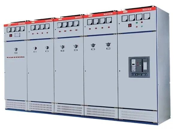
Product Overview
The GGD type AC low‑voltage distribution cabinet is suitable for AC 50Hz of power users such as power plants, substations, factories and mines. A power distribution system with a rated working voltage of 380V and a rated working current up to 3150A, used for power, lighting and distribution. It is used for the conversion, distribution and control of electrical energy in electrical equipment. The GGD type AC low‑voltage distribution cabinet is developed in accordance with the requirements of the superior authorities in charge of the Ministry of Energy, the majority of power users and the design department. The new type of low‑voltage distribution cabinet is designed based on the principles of safety, economy, rationality and reliability. The product has a high breaking capacity. It features good dynamic and thermal stability, flexible electrical schemes, convenient combination, strong series and practicality, novel structure and protection grade. It can be used as an updated product for low‑voltage switchgear assemblies.

SPECIFICATION
| Product Type | AC Low-Voltage Distribution Cabinet |
| Rated Frequency | AC 50Hz |
| Rated Working Voltage | 380V |
| Rated Current | Up to 3150A |
| Rated Insulation Voltage | 1000V |
| Rated Short-Circuit Breaking Current | 15kA / 30kA / 50kA |
| Installation | Indoor |
| Installation Altitude | ≤2000m |
| Ambient Temperature | -5°C to +40°C (24-hour average ≤35°C) |
| Relative Humidity | ≤50% at +40°C (higher humidity permitted at lower temperatures) |
| Protection Degree | IP30 (Optional: IP20 / IP40) |
| Standards | IEC 439, GB 7251 |
enforce standards
◆The GGD type AC low‑voltage distribution cabinet complies with IEC439 "Low‑voltage Switchgear and Controlgear Assemblies"
◆Standards such as GB 7251 "Low‑voltage Switchgear Assemblies".
Usage environmental conditions
◆The ambient air temperature shall not exceed +40℃ and shall not be lower than ‑5℃. The average temperature within 24 hours shall not exceed +35℃.
◆For indoor installation and use, the altitude of the usage site must not exceed 2000m.
◆The relative humidity of the surrounding air shall not exceed 50% at the maximum temperature of +40℃. A higher relative humidity should be allowed at lower temperatures (for example, 90% at +20℃), taking into account the temperature change may occasionally cause condensation.
◆The inclination of the equipment installation to the vertical plane shall not exceed 5°.
◆The equipment should be installed in a place free from severe vibration and shock, and where the electrical components will not be corroded.
◆When users have special requirements, they can negotiate and solve them with the manufacturer.
Technical parameters
◆Main circuit scheme The main circuit of the GGD cabinet is designed with 129 schemes, totaling 298 specifications (excluding the schemes and specifications derived from the functional changes of the auxiliary circuit and the changes in control voltage). Among them: There are 49 schemes and 123 specifications of GGD1 type. There are 53 schemes and 107 specifications of GGD2 type. There are 27 schemes and 68 specifications of the GGD3 type. The main circuit scheme was selected and compiled after soliciting opinions from a wide range of design and usage departments, adding the schemes required by power plants. Rated current up to 3150A, suitable for distribution voltage transformation of 2000KVA and below. Selection of equipment. In addition, to meet the requirements of reactive power compensation, GGJ1 and GGJ2 capacitor compensation cabinets were designed, with 4 main circuit schemes and a total of 12 specifications.
◆Auxiliary circuit scheme The design of the auxiliary circuit is divided into two parts: the power supply and consumption scheme and the power plant scheme. There is sufficient space in the GGD cabinet to install secondary components. Meanwhile, a dedicated LMZ3D type current mutual inductance has also been developed and researched. The device is designed to meet the needs of power plants and special users when they are equipped with relay protection.
◆Main busbar Considering the price ratio and the feasibility of using molybdenum instead of copper, single‑group busbars can be adopted when the rated current is 1500A or less, and double‑copper busbars can be used when the rated current is greater than 1500A. The manufacturer manufactures a prototype in accordance with this regulation and passes the type test. Of course, the manufacturer can also replace the aluminum busbars with copper busbars of the same cross‑section according to the user's requirements. The lap surfaces of the busbars are all treated with tin‑plating process.
◆Selection of electrical components The GGD cabinet mainly adopts relatively advanced electrical components that can be mass‑produced domestically. At the same time, in accordance with the principles of economy and rationality, and fully considering feasibility, it retains some available old products such as DZ10D and DZ20, and does not select products that have been phased out. The HD13BX and HS13BX type rotary operation knife switches are dedicated components designed to meet the unique structural requirements of GGD cabinets. They have changed the operation mode of the mechanism, retained the advantages of the old products, and are a new type of practical electrical component.
Structural characteristics
The cabinet body of the GGD type AC low‑voltage distribution cabinet adopts the form of a general‑purpose cabinet. The frame is assembled by local welding of 8MF cold‑formed steel sections. The frame parts and special matching parts are supplied by the designated steel section production factory to ensure the accuracy and quality of the cabinet body. The components of the general cabinet are designed based on the module principle and have 20 installation holes. The high universal coefficient enables factories to achieve pre‑production, which not only shortens the production and manufacturing cycle but also improves work efficiency.
When designing the GGD cabinet, full consideration was given to the heat dissipation issue during the operation of the cabinet. There are different numbers of heat dissipation slot holes at both the upper and lower ends of the cabinet. When the electrical components inside the cabinet heat up, the hot air rises and is discharged through the upper slot holes, while the cold air continuously replenishes the cabinet through the lower slot holes, forming a natural ventilation channel from bottom to top in the sealed cabinet, achieving the purpose of heat dissipation.
The GGD cabinet is designed in accordance with the requirements of modern industrial product shape design, using the golden ratio method to design the cabinet's shape and the division dimensions of each part, making the entire cabinet elegant and stylish, with a brand‑new look. The cabinet door is connected to the frame with a swivel hinge, which is convenient for installation and disassembly. A mountain‑shaped rubber and plastic strip is embedded in each folded edge of the door. When closing the door, the embedded strip between the door and the frame has a certain compression stroke, which can prevent the door from directly colliding with the cabinet body and also improve the protection level of the door. The instrument door equipped with electrical components is connected to the frame with multi‑strand soft copper wire. The installation parts inside the cabinet are connected to the frame with knurled screws.
The entire cabinet forms a complete grounding protection system. The surface paint of the cabinet body is made of polyester orange varnish, which has strong adhesion, good texture, and a dry matte tone throughout the cabinet, avoiding the dazzling effect and creating a more comfortable visual environment for the on‑duty personnel. The top cover of the cabinet can be removed when necessary to facilitate the assembly and adjustment of the main busbar on site. Lifting rings are installed at the four corners of the cabinet top for lifting and transportation. The protection grade of the cabinet is IP30. Users can also choose between IP20 and IP40 according to the requirements of the usage environment.
Installation and Usage
After the products arrive at the delivery location, the first thing to do is to check whether the packaging is intact and undamaged. If any problem is found, the relevant department should be informed in time to find out the cause. For products that are not installed immediately, they should be placed in appropriate locations in accordance with the provisions of normal usage conditions.
◆Product installation
The installation of the product should be carried out in with the installation schematic diagram (see attached Figure 2), and the foundation channel steel and bolts shall be prepared by the user themselves. When installing the main busbar in a row with tin‑plating, the lap surface should be repaired and leveled, cleaned thoroughly, coated with neutral Vaseline or other measures taken, and then fastened with bolts. Before the product is put into operation after installation, the following items need to be inspected and tested:
- Check if the surface paint of the cabinet has peeled off and if the interior of the cabinet is dry and clean.
- Check whether the operating mechanism of the electrical components is flexible and there should be no jamming or excessive operating force.
- Whether the on‑off of the main and auxiliary contacts of the main electrical appliances is reliable and accurate.
- Whether the instrument indication and the ratio and polarity of the transformer are correct.
- Whether the busbar connection is good, and whether the insulating support parts, installation parts and accessories are installed firmly and reliably
- Whether the auxiliary contacts meet the requirements, whether the fuse specification of the fuse is correct, whether the setting value of the relay meets the design requirements, and whether the action is reliable and accurate
- Whether the contacts of the circuit comply with the requirements of the electrical schematic diagram.
- Whether the protection circuit system meets the requirements. The insulation resistance value measured with a 500‑volt megohmmeter must not be lower than 1MΩ.
◆Precautions for Use
1.This product is a single‑sided (front), double‑sided door maintenance low‑voltage distribution cabinet that is not installed against the wall. The maintenance passage and cabinet doors of the product can only be entered or opened by professionals who have passed the assessment for operation, inspection and maintenance.
2. After multiple closing and opening operations, the main contacts of the air circuit breaker will be burned at the same part and carbon will be produced, increasing the contact resistance. Regular maintenance and inspection of the air circuit breaker should be carried out in accordance with its user manual.
Hot Tags: low-voltage switchgear ggd type, China, suppliers, manufacturers, factory, customized, quotation


